
Body & doors
Dimensions, material, sheet thickness, doors and seal define the enclosure.
Digital engineering for enclosures
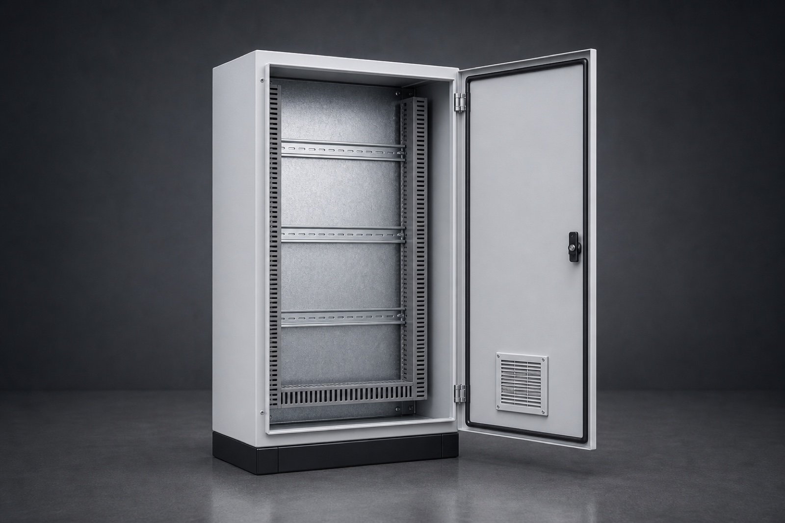
Dimensions, material, protection class, doors, mounting plates, cut-outs, ventilation and accessories are selected on a real 3D assembly—with plausible geometry for quotation and production.
From installation space to a production-ready variant
Enclosure errors often occur at interfaces: door swing, mounting plate, ventilation, cable entry and machining. The configurator makes these dependencies visible and verifiable.
Design, dimensions, material, door count and protection class define the base enclosure.
Mounting plates, rails, fans, cable entries and customer-specific cut-outs are added with product rules.
The configuration delivers a view, specification, BOM and optional STEP and DXF data.
Customer, sales and production work with the same dimensions, machining and accessory positions.
Recent confBuild projects
confBuild connects parametric sheet-metal geometry, assemblies and accessory logic—from a simple wall box to a freestanding cabinet.
This could be your product ↗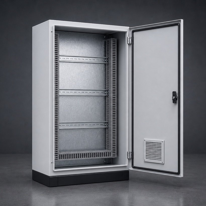
Compatibility instead of accessory lists
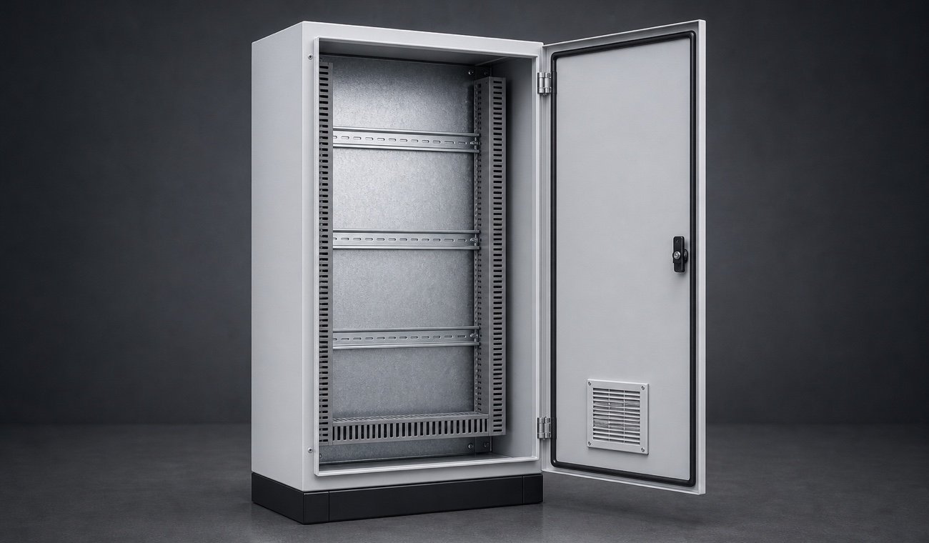
Body, door, seal, mounting plate, DIN rails, cable paths, ventilation and machining follow one shared rule set.
Map my product system ↗Dimensions, material, sheet thickness, doors and seal define the enclosure.
Holes, cut-outs, ventilation fields and cable entries are validated with edge clearances.
Mounting plate, DIN rails, cable ducts and accessories remain geometrically compatible.
STEP, DXF, BOM and specification can be derived from the same variant.
Dimensions, material, sheet thickness, doors and seal define the enclosure.
Holes, cut-outs, ventilation fields and cable entries are validated with edge clearances.
Mounting plate, DIN rails, cable ducts and accessories remain geometrically compatible.
STEP, DXF, BOM and specification can be derived from the same variant.
From custom size to manufacturing-ready specification
The workflow connects product selection, machining and compatible accessories without media breaks.
Powered by the confBuild CAD kernel
The confBuild CAD kernel generates body, doors and internal fit-out from dimensions and rules. Change width and mounting plate, rails, cable paths and machining positions respond consistently.
Experience the CAD kernel →The same parameters reliably produce the same geometry—reproducible instead of merely similar.
Parts and accessories remain connected through clear dependencies and product rules.
Structured parameters and component data can feed enquiries, BOMs and subsequent workflows.
Interactive in the web browser—without local CAD installation and directly in your sales experience.
More than a beautiful 3D view
The configurator closes the gap between product catalogue, customer-specific machining and manufacturing-ready data output.
Check the potential for my range →Only accessories that fit the enclosure and installation space are offered.
Cut-outs, doors and internal fit-out become visible before ordering.
Specification and BOM are ready without manual transfer.
STEP and DXF can emerge from the same rule-based geometry.
Focused remote pilot
We capture dimensions, accessories, machining rules and outputs for one product family.
We build the 3D model, placement logic and data handovers as a focused pilot.
The pilot is refined with real customer cases from sales and production planning.
Ready for digital manufacturing proximity?
In 20 minutes we identify the enclosure family best suited to a productive pilot.
Contact
Briefly describe your product or assembly – you will get a reply within one business day.
Prefer plain email? daniel@confbuild.com
Prefer to talk? Book a 30-minute call →
A service by confbuild.com – parametric 3D configurators for your product.
Book a call
Choose a free 30-minute slot. You get a calendar invitation right away – no sign-up, no back and forth.
Prefer to write? Go to the contact form
Loading available times …
Please pick a day first.
The calendar invitation is on its way to your inbox. It also contains a link to cancel the appointment.